
NT4
After this, be sure to see: NT/5
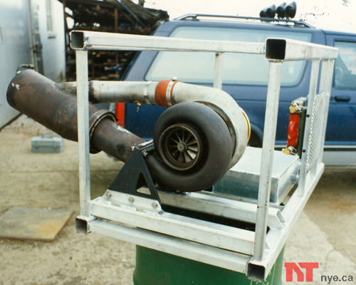
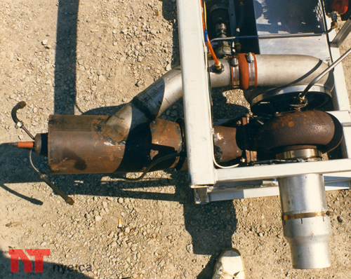
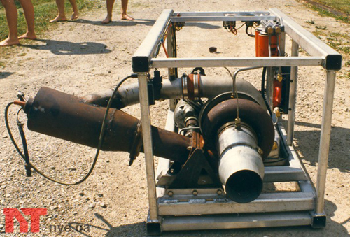
In the early 80's, my interest in turbo turbines was rekindled. NT/4 is basically the same turbo/combustor arrangement as NT/3, but this time mounted in a proper test frame.

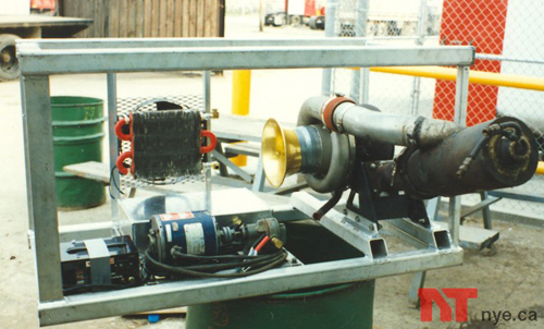
NT/4 at the shop - These photos show the jet mounted in the uncompleted test rack. The motor mounts are made of flame cut 1/4" steel plate. Notice my 86 Blazer in the background, nice little truck, but it only had a little 2.8 L engine.

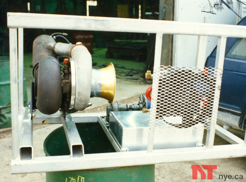
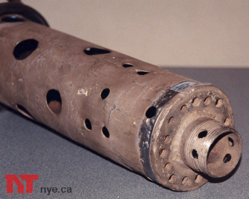
The business end! - Here you can see the make-shift exhaust nozzle, and the EGT thermocouple.
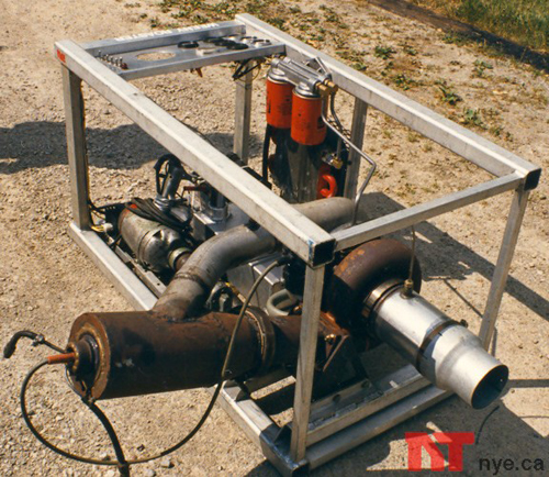

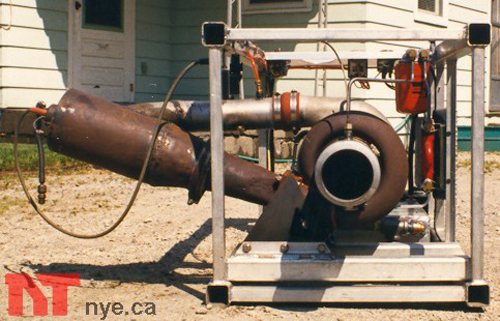
Yes, the combustor is too long - we made it extra long to make sure there was a generous dilution zone, to keep flames off the turbine during development. The final version would be much shorter and made of stainless steel.

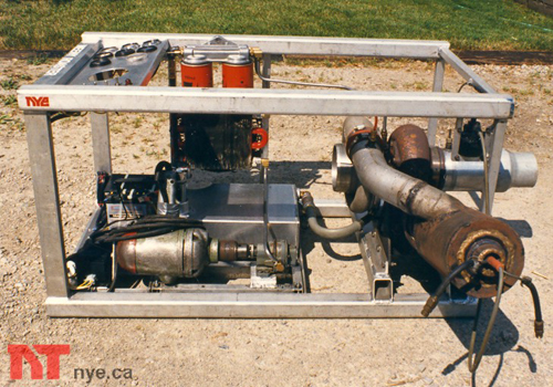

NT/4 - on the driveway at home.
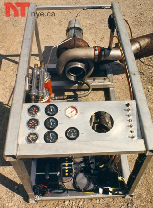
The oil pump is driven by a ¾” electric drill in the lower left. The twin oil filters and oil cooler are in the upper left. The GM HEI coil is mounted in the upper right. (follow the 8mm wire to the spark plug in the end of the combustor). In one view you can see the control panel, the big hole is for the yet to be developed tach. The motorcycle battery is connected to a Honda CBX starter motor, equipped with a 9/16 deep socket. Cranking is controlled by a Ford solenoid and a push-button mounted on the side of the starter. The thermocouple wires for the EGT pyrometer can be seen leading directly up from the turbine.
APU
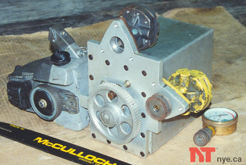
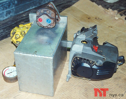
These are the components for the APU (auxiliary power unit). The aluminum oil tank houses a Honda CBX oil pump, the front cover provides mounting flanges for the two Detroit diesel fuel pumps. The larger of the two pumps is for the after burner, we actually made one, do you know what a mach diamond is? All three pumps were to be driven by a cogged timing belt, powered by a modified Mac 140 chain saw engine.

Here’s me with the old Margay racing go-cart that was given to me. Phil and I lengthened the frame to fit the APU and jet. We intended to use the jet thrust for propulsion. We were also thinking about using the exhaust turbine from another turbo as a power turbine, add a home made gearbox and we would have a powerful free-shaft gas turbine that could drive the wheels! The go-cart was a piece of junk, but we’ve had fun thinking about how fast it would go, and what it would sound like.
NT/4 Combustor casing.
NT/3 - Combustor liner.

Our first removable fuel and igniter module.
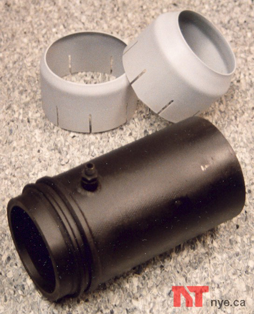
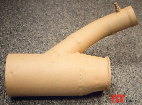
Tail pipe with replaceable nozzles.
We have no thrust data for NT/4, no measurements were taken. We were more interested in systems and operation than performance.
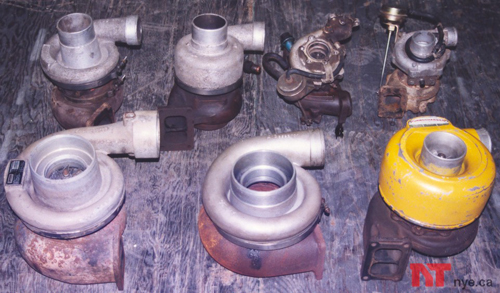

Our turbo collection.
This jet sat in the corner of my garage at home for quite some time. The turbine was damaged slightly by a piece of the combustor that melted off during a hot start. In order to proceed properly, a reliable tachometer was needed. If the turbine blows-up due to N1 over-speed, then we need to know what speed it went at, so we don’t do it again.
We have done some experimenting with a home made tachometer, a simple pulse counter on a breadboard with a fiber-optic probe, a Motorola MFOD71 phototransistor and a LASER. We aimed the LASER at the compressor wheel and used the probe to pickup the reflected pulses from the blades. We used a LM386 op-amp to amplify the signal from the phototransistor, and measured the output on an oscilloscope. We had a hard time getting it all to work, I did measure a peak N1 speed of 85,000 RPM once, but the oscilloscope screen was hard to see in the sunlight, and with fuel lines, wires and fiber-optics crisscrossing in all directions, We decided that if we were to proceed, the only sensible thing to do would be to purchase a commercial sensor probe and digital display and for this, we had no money.
Until recently...
If you like what you have seen so far, check out our subsequent project; The NT/5 TurboJET
![]()